搜尋
搜尋結果
搜尋AMI Modem Card ,
共找到 15 筆
- 排序
- 依時間
- 依熱門度

培訓
工具
學習
影片長度 - 3:23
Demonstrate how to use the ICP Programming Tool to generate a programming file, and use the PC to save the firmware to the USB/SD storage device, insert the USB/SD storage device into Nu-Link2-Pro, and then connect the target chip, press the trigger button to complete offline programming.
-
For more information, please visit Nuvoton Technology Website: https://bit.ly/3hVdcmC
Buy now: https://bit.ly/3bk0AD8
Contact us: SalesSupport@nuvoton.com
#en #Tool #Training #Intermediate #Learning

培訓
工具
學習
影片長度 - 3:24
Hello everyone I am Chris, the Field Application Engineer from Nuvoton Technology.
Today I will introduce the programming and debugging tool, called NuLink-Gang, and NuLink2-Pro. And I will show you in what kind of situation you can utilize the tools.
During system development, Nuvoton provides three IDE interfaces: KEIL, IAR, and NuEclipse for user to develop source code.
When programming the Chip, Nuvoton provides ICP programming Tool in PC and the debugger Nu-Link2-Pro for users to perform debugging and programming function.
User who uses all of the Nuvoton Nu-Maker boards series can develop through the Nu-Link2-Me debugger and programmer; it’s attached to the board.
During the mass-production stage, there are 2 modes for programming the target chip. One is online programming and the other is offline programming.
At first, in online programming mode, user can use ICP programming Tool and a Nu-Link2-Pro to program a target chip. Besides, if it needs to program several chips at one times, the Nu-Link Command Tool supports program multiple develop board by several Nu-Link2-Pro.
Nu-Link2-Pro also supports drag-and-drop Flash programming. User can intuitively complete the programming action.
Nu-Link2-Pro
In offline programming mode, user can pre-store the programming file in SPI flash, USB flash drive, or SD card. When user wants to program the target chip, pressing the programming button on Nu-Link2-Pro to complete the programming action.
If it needs a large number of ICs to be programming, it recommends using the Nu-Link-Gang programmer. Nu-Link-Gang programmer can perform offline programming on four different chips at a time, significantly increasing the programming efficiency. Besides, Nu-Link-Gang programmer can also use the control bus to connect with an automatic programming machine for automatic programming.
In the system upgrade, Nu-Link2-Pro also provides five standard communication interfaces such as SPI, I2C, UART, RS485, and CAN for transmission, which is convenient for users to upgrade the system.
That’s all for the introduction of Nuvoton’s programming and debugging tool, NuLink-Gang, and NuLink2-Pro. Thank you for watching it. If you want to know more details, please contact us! Thank you.
#Tool #Training #Learning #Intermediate #en
-
For more information, please visit Nuvoton Technology Website: https://bit.ly/3hVdcmC
Buy now: https://direct.nuvoton.com/numaker-m251sd
Contact us: SalesSupport@nuvoton.com
培訓
工具
學習
影片長度 - 5:0
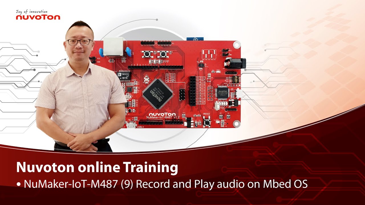
Hello everyone, I am Morgan, the principal engineer of Nuvoton Technology. Today, I will show you how to record and play audio with Mbed OS on NuMaker-IoT-M487 development board.
Open Chrome browser, and enter the URL https://ide.mbed.com to use the Mbed Online Compiler.
After log in, make sure that NuMaker-IoT-M487 board already selected in the upper right corner. If not, please refer Nuvoton IoT Tutorial series “Get Started with Mbed OS” which has a detailed description of how to add a board.
Click the “New” on the left of menu bar, a “Create new program” window will be displayed.
You can see that the Platform has been set to NuMaker-IoT-M487. In the Template, select the "NuMaker audio playback" for this tutorial. Then click OK.
Now you can see that the sample code has loaded on the page.
The sample code has three functions:
1. Record 10 seconds sound and save to Micro SD card
2. Play sounds stored in Micro SD card
3. Loopback. Record sound and play it immediately.
Click main.cpp to open it. Then scroll down to line 421. You can see the functions calls here. It set to loopback only.
Let’s do a little modification. Hit a key on console to start record 10 seconds then play it, and then do loopback.
printf("Press a key to start recording 10 seconds...");
getchar();
demo_record();
demo_play();
demo_loopback();
Save it and click “Compile” to build the code.
Compilation takes a while, please wait.
After the compilation is completed, “Success” will appear in the compile output window.
The browser downloads the binary firmware file directly after a successful compiling. It will be saved in a default download folder. In Chrome, you can click download file and select “Show in folder”.
Please plug an earphone commonly used for mobile phone in headphone jack on NuMaker-IoT-M487 board. For demonstration, we use a headphone splitter cable to connect a microphone and a speaker. Do not put the microphone and speaker too close to avoid feedback howling. Then connect the USB port to your computer and make sure the onboard LED lights up.
Back to the folder you just download the binary firmware file (NuMaker-mbed-AudioPlayback-example.NUMAKER_IOT_M487.bin). Drag and drop the file to NuMicro MCU drive.
You will see the copying progress dialog box.
Please find the virtual COM port assigned for NuMaker-IoT-M487 in Device Manager. In the demonstration, the “Nu-Link Virtual Com Port” is COMx.
Then use your favorite terminal tool. Here we use Putty. Open the COMx port with 9600 baud rate.
And no flow control settings. Then “Open” it.
Press “Reset” on board to run the firmware again.
Press a key on terminal to start record.
Speak for about 10 seconds, then your voice will be played.
That’s all for this tutorial. Thank you for watching.
Welcome to subscribe to our channel.
If you want to get more information, please contact us “SalesSupport@nuvoton.com”
-
For more information, please visit Nuvoton Technology Website: https://bit.ly/3hVdcmC
Buy now: https://direct.nuvoton.com/tw/numaker-iot-m487
Contact us: SalesSupport@nuvoton.com
#tool #training #learning #intermediate #en

培訓
工具
學習
影片長度 - 3:55
Hello everyone, I am Morgan, the principal engineer of Nuvoton Technology. Today, I will show you how to use SD card with Mbed OS on NuMaker-IoT-M487 development board.
Open Chrome browser, and enter the URL https://ide.mbed.com to use the Mbed Online Compiler.
After log in, make sure that NuMaker-IoT-M487 board already selected in the upper right corner. If not, please refer Nuvoton IoT Tutorial series “Get Started with Mbed OS” which has a detailed description of how to add a board.
Click the “New” on the left of menu bar, a “Create new program” window will be displayed.
You can see that the Platform has been set to NuMaker-IoT-M487. In the Template, select the "NuMaker SD-File-System with SD mode" for this tutorial. Then click OK.
Now you can see that the sample code has loaded on the page. LittleFS uses less memory, supports power failure protection. However, LittleFS is different from the FAT file system, so after uses littleFS, the SD card will be formatted as LittleFS. The sample code uses FAT file system as default.
Just click “Compiler” to build the example.
It is in compiling, please wait a moment.
After the compilation is complete, “Success” will appear in the compile output window.
The browser downloads the binary firmware file directly after a successful compiling. It will be saved in a default download folder or the folder based on your browser setting. In Chrome, you can click download file and select “Show in folder”.
Please insert a micro SD card into the card slot on the back of NuMaker-IoT-M487 board, then connect the USB to your computer and make sure the onboard LED lights up.
Let’s back to the folder you just download the binary firmware file (NuMaker-mbed-SD-FileSystem-example.NUMAKER_IOT_M487.bin). Drag and drop the file to NuMicro MCU drive.
You will see the copying progress dialog box.
Please find the virtual COM port assigned for NuMaker-IoT-M487 in Device Manager. In the demonstration, the “Nu-Link Virtual Com Port” is COMx.
Then use your favorite terminal tool. Here we use Putty. Open the COMx port with 115200 baud rate
And no flow control settings. Then “Open” it.
Press “Reset” on board to run the firmware again.
You can see the messages on terminal while accessing SD card.
That’s all for this tutorial. Thank you for watching.
Welcome to subscribe to our channel.
If you want to get more information, please contact us “SalesSupport@nuvoton.com”
-
For more information, please visit Nuvoton Technology Website: https://bit.ly/3hVdcmC
Buy now: https://direct.nuvoton.com/tw/numaker-iot-m487
Contact us: SalesSupport@nuvoton.com
#tool #training #learning #intermediate #en

前瞻應用
學習
影片長度 - 3:42
以新唐 NuMaker-IoT-M263A 為平台,使用 Mbed OS 進行開發,學習各種功能。觀看本片,您將學會使用 NuMaker-IoT-M263A 開發板配合 Mbed OS 範例程式存取 SD 記憶卡。
哈囉大家好,我是新唐工程師 Miya,今天為大家介紹如何使用新唐 NuMaker IoT-M263A 在 MbedOS 使用 SD Card。
首先打開 Chrome 瀏覽器,輸入網址 "https://ide.mbed.com/",登入後先確認右上方板子已經有帶出 “NuMaker-IoT-M263A 及板子小圖示” 了,如果沒有可參考教學影片 “step by step 讓你了解如何運行 Mbed OS”,裡面有詳細的示範怎麼新增板子的方法。首先點選左上方的 “New”,會載入一個 Create new program 的小視窗,可以看到 Platform已經帶出 NuMaker-IoT-M263A,在 “Template” 這欄選取 sample code,使用 NuMaker SD-File-System with SD mode 這個 sample,點一下 OK。
現在可以看到 sample code 已經載入頁面,這個範例預設採用 FAT file system,LittleFS 佔用比較少的記憶體,支援斷電保護,但 LittleFS 與 FAT file system 不同,若允許格式化 SD 卡及變更原本 SD 卡的 FAT file system 為 LittleFS,可執行修改 main.cpp 的動作。在這版本的第 34 到 40 行的地方,可以看到說明這個 example code內定是用 FAT file system,若要改成使用 LittleFS,就可先將預設的 FAT file system 設定在第 35 及第 36 行改為註記,接著將第 39 及 40 行的註記符號刪除。教學影片示範編譯的檔案是使用 FAT file system,程式碼不需更動,所以這邊將剛才的示範改回。確認程式碼中設定的檔案格式後存檔,按 Compile 編譯程式,編譯中需要等待一下,編譯完成後下方會出現 “success!”。
系統會把編譯完成的 bin 檔放在 download 資料夾,直接從下方進入,上拉後點一下 “Show in folder”,到預設的 download 夾。先確認已將 micro SD Card 插在板子後,再將 NuMaker-IoT-M263A 板子跟 PC 接上 USB,確認板子有亮燈就是通電了。回到 download 資料夾,可以看到多了一個剛才 compile 完成的 bin 檔,按右鍵傳送到 NuMicro MCU(E:),這邊分配到哪一槽要看各位的電腦決定,有成功點選到的話會出現傳送過去的畫面。
到電腦的裝置管理員查看分配到的 port 編號,在本機按右鍵,點裝置管理員,找到連接埠 (COM 和 LPT),找到 USB 序列裝置,就可以知道像這部 PC 分配給它的是 COM12。接下來使用終端機模擬軟體,各位可以用自己熟悉的軟體操作即可,設定 Serial line 為 COM12,Speed 為 115200,到 Serial 將 Flow control 改為 None,接著 OPEN。設定好之後在板子上按一次 reset,接著在終端機摸擬軟體就可以看到系統回傳測試 SD Card 的資料。
以上是這次的教學影片,感謝您的收看,如果您想知道更多資訊歡迎聯絡我們。
-
更多產品資訊,請至新唐科技網站 https://bit.ly/3hVdcmC
購買管道:https://direct.nuvoton.com/tw/numaker-iot-m263a
聯絡我們: SalesSupport@nuvoton.com
#application #learning #intermediate #zh-Hant
培訓
工具
學習
影片長度 - 8:37
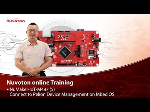
NuMaker-IoT-M487 (5)
Connect to Pelion Device Management on Mbed OS
Hello everyone, I am Morgan, the principal engineer of Nuvoton Technology. Today, I will show you how to connect to Pelion Device Management with Mbed OS on NuMaker-IoT-M487 development board.
Because the demonstration needs to store certificate, a MicroSD card is required.
Open Chrome browser, enter the URL https://cloud.mbed.com/quick-start
If you didn’t use Pelion Device Management before, you need to activate your Mbed account to access Pelion. Click the “Activate your free access”. Then log in your Mbed account.
Click “Activate Pelion Device Management account“…
Select the “Start the Connect Tutorial”
Then scroll down to select NuMaker-IoT-M487 (WiFi)
--After selected, scroll down and click “Get started”--
If you have completed previous tutorial, the NuMaker-IoT-M487 board has been selected in your Mbed account.
Please click the “2.2” to import the Pelion Connect Tutorial into your Online Compiler.
It shows the import dialog box, please click Import.
Wait for a moment while importing the sample code.
Click “mbed-os-example-pelion” project name,
Then click “Pelion Device Management” on menu bar, select “Manage Connect Certificates” in pull-down menu to create a Pelion certificate.
You need to provide API key. You can create a new one here.
Log in your mbed account.
Accept
Then click New API key
Assign an API Key name
Click Close
After created an API key, back to online compiler,
Then click Manage Connect Certificate again.
API Key automatically filled here.
Click OK.
Click “Create”, then assign a name for the certificate.
Click OK.
Click the certificate just created to select it, then click OK.
The online compiler will automatically update source code with the selected certificate.
Click “Pelion Device Management” on menu bar again, select “Apply Update Certificate”. An “Update Certificates” dialog box appears. Create it.
Click Download Private Key and save it.
Please make sure that NuMaker-IoT-M487 board already selected in the upper right corner. If not, please refer Nuvoton IoT Tutorial series “Get Started with Mbed OS” which has a detailed description of how to add a board.
In order to use Wi-Fi, you have to configure SSID and password to match your Wi-Fi access point setting.
In the mbed_app.json file, the default Wi-Fi security set to WPA and WPA2 in “nsapi.default-wifi-security” field. Please modify the field “nsapi.default-wifi-ssid” to your Wi-Fi SSID
Then modify “nsapi.default-wifi-password” to your Wi-Fi password.
Click on “Compile” to build it. Have to wait for a while.
Then you can see the last message is “Success!” at the bottom of this page.
The browser will download the binary firmware file directly after a successful compiling. It will be saved in a default download folder or the folder based on your browser setting. In Chrome, you can click download file and select “Show in folder”.
Then we connect the NuMaker-IoT-M487 USB port to your computer and make sure the onboard LED lights up.
Let’s back to the download folder where you can see the binary firmware file (mbed-os-example-pelion.NUMAKER_IOT_M487.bin). Drag and drop the file to NuMicro MCU drive.
You will see the copying progress dialog box.
Please find the virtual COM port assigned for NuMaker-IoT-M487 in Device Manager. In the tutorial, the “Nu-Link Virtual Com Port” is COMx.
Then use your terminal tool. Here we use Putty. Open the COMx port with 115200 baud rate, 8 bits, 1 stop bit, none parity, and no flow control settings.
Then “Open” it.
Press Reset button on board to run again.
You can see the connection messages printed on terminal. It shows the board’s IP address obtained from the Wi-Fi access point, and the Endpoint Name.
Then you can see the device resource in Pelion Device Management Portal.
Log in Pelion Portal with the same Mbed account.
Click Device directory. Find the device ID which should be registered state.
Click the Device ID, it shows the Device details.
Click RESOURCES, find the resource 3200/0/5501. Click the resource.
Now, you can press keys in terminal to increase the counter. Or the counter automatically increase 1 by one second. The demo code also updates the counter to Pelion. You will see the value change in the graph.
That’s all for this tutorial. Thank you for watching. Welcome to subscribe to our channel. If you want to know more information, please contact us at SalesSupport@nuvoton.com
-
For more information, please visit Nuvoton Technology Website: https://bit.ly/3hVdcmC
Buy now: https://direct.nuvoton.com/tw/numaker-iot-m487
Contact us: SalesSupport@nuvoton.com
#tool #training #learning #intermediate #en

前瞻應用
學習
影片長度 - 4:49
以新唐 NuMaker-IoT-M263A 為平台,使用 Mbed OS 進行開發,學習各種功能。觀看本片,您將學會使用 NuMaker-IoT-M263A 開發板配合 Mbed OS 與 Pelion 的範例程式連接 Pelion 裝置管理雲端。
哈囉大家好,我是新唐工程師 Miya,今天為大家介紹如何使用新唐 NuMaker IoT-M263A在 MbedOS 上連接 Pelion 雲端。
因為需要將下載後的憑證儲存於 MicoSD Card
所以操作前需要先將 MicoSD Card 置入卡槽中
。
接著請打開 Chrome 瀏覽器,輸入網址
https://cloud.mbed.com/quick-start
。需要先啟動免費帳號
點選中間上方 Activate your free access
,系統開啟的下一個頁面直接點 Log in ,
輸入您的帳號密碼登入
。啟動後選擇中間選項
Start the Connect Tutorial
,系統會自動轉到這個頁面,
往下拉選取 NuMaker-IoT-M263A
,系統將導入此頁面,
點選 2.1 將 M263A 加進線上編譯平台。加入後系統會自動新增確認頁面,
告知板子已被加入平台,
接著點選 2.2
將 mbed-os-example-pelion 加入線上編譯平台
,確認系統匯入 mbed-os-example-pelion 後
點 Import,
Load code 中
請稍待片刻。
Load code 完成後,可以看到系統
已將 Sample code 載到頁面裡了
,先點選 mbed-os-example-pelion program
,接著在 Online compiler IDE 環境的 menu bar 上,
到 Pelion Device Management 中,
下拉選取 "Manage Connect Certificates
" 來建立 Pelion 憑證
。在跳出的 API Key 小視窗
按一下 OK,點 Create
,幫您的連接憑證命名
輸入好之後,按OK
。點選剛才建立的憑證
再按 OK,
確認後點 OK 。
點 Pelion Device Management
,選取 Apply Update Certificate,
會出現 Update Certificates 視窗
,按Create,
點 Download Private Key
。
由於要使用 Wi-Fi
,所以需要將 SSID 及密碼
,改成可符合您連線環境的設定
。找到 mbed_app.json 裡面 SSID 設定 "wifi-ssid"
,此版 sample code 在第 22 行
,更改為您使用無線網路所設定的 SSID
。接著再找到 "wifi-password",設定
此版在第 23 行裡的 Password
,改成您無線網路連接設定的密碼
,改好後存檔
。Compile。,現在 Compile 中
需要等待一下,
完成後看到最下方會秀出 "Success!"
。
系統會把 compile 完成的 bin 檔
放在 download 資料夾,
直接從下方進入,
上拉後點一下 "Show in folder"
。接著將 NuMaker-IoT-M263A 板子透過 USB 接上 PC
,確認板子有亮燈就是通電了。
回到剛才的資料夾,
可以看到多了一個剛才 compile 完成的 bin 檔
,按右鍵傳送到 NuMicro MCU(F:)
,這邊分配到哪一槽要看各位的電腦決定,
有成功點選到的話,會出現傳送過去的畫面。
接著到電腦的裝置管理員,查看分配到的 port 編號,
在本機按右鍵
選管理
,找到裝置管理員,
到連接埠 (COM和LPT)
,可以看到 USB 序列裝置
,就知道這部 PC 分配給它的是 COM12
。
接下來使用終端機模擬軟體,
各位可以用自己熟悉的軟體操作即可
。設定 Serial line 為 COM12,
Speed 為 115200
,到 Serial 將 Flow control 改為 None
,接著 OPEN
。設定好之後
在板子上按一次 reset。
接著在終端機摸擬軟體,就可以看到
目前板子已經成功連接無線網路
,看到雲端回傳的 Endpoint name,就代表連接成功囉
!以上是這次的教學影片,
感謝您的收看
,如果您想知道更多資訊,
歡迎聯絡我們。
-
更多產品資訊,請至新唐科技網站 https://bit.ly/3hVdcmC
購買管道:https://direct.nuvoton.com/tw/numaker-iot-m263a
聯絡我們: SalesSupport@nuvoton.com
#application #learning #intermediate #zh-Hant

培訓
工具
學習
影片長度 - 8:36
Hello everyone, I am Morgan, the principal engineer of Nuvoton Technology. Today, I will show you how to use 4G LTE or NB-IoT with Mbed OS on NuMaker-IoT-M487 development board.
This tutorial needs a cellular expansion board to work with NuMaker-IoT-M487 development board. You can purchase the 4G LTE expansion board, RF-EC21A, on Nuvoton Direct (https://direct.nuvoton.com/communication-module/). Please install your 4G LTE SIM card in the mini SIM card slot on the back, and install the antenna at the MAIN connector on the front of the board.
Although there is an NB-IoT expansion board, it requires an NB-IoT SIM card. Using LTE is more convenient. Just use your own LTE SIM card which has data plan.
Then install the expansion board to the Arduino UNO connector of the NuMaker-IoT-M487 development board.
Because the power consumption of the 4G LTE module is higher, it is not enough to supply power from USB only. You need to plug in the 5V/2A power supply. If you use NB-IoT module, no additional power supply is needed.
We used “New” to select a template to create a new project. This time, we use the example on GitHub to create a new project. The URL of template used for this tutorial is https://github.com/OpenNuvoton/NuMaker-mbed-Cellular-example
In chrome browser, enter the URL https://ide.mbed.com to use Mbed Online Compiler environment.
After you log in, make sure that NuMaker-IoT-M487 board already selected in the upper right corner. If not, please refer Nuvoton IoT Tutorial series “Get Started with Mbed OS” which has a detailed description of how to add a board.
Click the second option “Import” on the upper left.
In the Import Wizard, click “Click here”
On the “Source URL:”, enter the tempalte URL https://github.com/OpenNuvoton/NuMaker-mbed-Cellular-example . Then move mouse cursor to “Import Name:” and click it, the Project name will be automatically fill in. Then click “Import” button.
Now you can see that the sample code has loaded. Depending on the cellular module used, the configuration may need to be modified. Click on “Readme.md” to open it. It lists configurations for supported cellular modules.
Because the tutorial uses RF-EC21A expansion board which includes a Quectel EC21 LTE module, let’s check and modify the configuration in mbed_app.json file.
Click the “mbed_app.json” file to open it. It is a JSON file to customize compile time configuration parameters in Mbed OS. The “*” (asterisk) in “target_overrides” session indicates all development boards are applicable. You can set in the designated board session, so the settings are only applicable to the specified board.
The default mbed_app.json file in the example has configured for RF-EC21A. Such as,
"target.network-default-interface-type" has set to "CELLULAR" for cellular connection.
Both "lwip.ppp-enabled” and "lwip.tcp-enabled" set to true.
Use generic AT3GPP driver for RF-EC21A ("GENERIC_AT3GPP.provide-default": true)
And the RF-EC21A UART connects on Arduino D0/D1 ("GENERIC_AT3GPP.tx": "D1" and "GENERIC_AT3GPP.rx": "D0")
When your SIM card installed in your mobile phone, you can find the APN, username and password settings in your mobile phone. Or contact your telecom operator to get this information. In the example, APN has set to “internet”, no username, and no password. (Move mouse cursor around these settings)
The final setting to check is PIN code. In the example, the setting is no PIN code. If your SIM card has PIN code, for example 1234, please set it like this “\”1234\”” (Move mouse cursor around the setting)
Save it then build it.
It is in compiling, please wait a moment.
Then you can see the last message is “Success!”.
The browser will download the binary firmware file directly after a successful compiling. It will be saved in a default download folder or the folder based on your browser setting. In Chrome, you can click download file and select “Show in folder”.
Then we connect the NuMaker-IoT-M487 USB port to your computer and don’t forget to plug in external 5V power supply.
Please find the virtual COM port assigned for NuMaker-IoT-M487 in Device Manager. In the demonstration, the “Nu-Link Virtual Com Port” is COMx.
Then use your favorite terminal tool. Here we use Putty. Open the COMx port with 115200 baud rate, 8 bits, 1 stop bit, none parity, and no flow control settings. Then “Open” it.
Let’s back to the download folder where you can see the binary firmware file (NuMaker-mbed-Cellular-example.NUMAER_IOT_M487.bin). Drag and drop the file to NuMicro MCU drive.
You will see the copying progress dialog box.
You can see the connection messages printed on terminal. It shows that the board creates a TCP connection to server “echo.mbedcloudtesting.com”, send 4 bytes data and get the data back from server.
That’s all for this tutorial. Thank you.
For more information, please visit Nuvoton Technology: https://bit.ly/3hVdcmC
Buy now: https://direct.nuvoton.com/tw/numaker-iot-m487
#tool #training #learning #intermediate #en

培訓
工具
學習
影片長度 - 3:50
以新唐 NuMaker-IoT-M487 為平台,使用 Mbed OS進行開發,學習各種功能。觀看本片,您將學會使用NuMaker-IoT-M487開發板配合Mbed OS 範例程式存取 SD 記憶卡。
哈囉! 大家好,我是新唐工程師Miya,今天為大家介紹如何使用新唐NuMaker IoT-M487在MbedOS使用SD Card。
首先打開Chrome瀏覽器,輸入網址"https://ide.mbed.com/"。
登入後先確認右上方板子已經有帶出”NuMaker-IoT-M487及板子小圖示”了,如果沒有可參考教學影片”step by step讓你了解如何運行Mbed OS”,裡面有詳細的示範怎麼新增板子的方法!
首先點選左上方的”New”,會載入一個Create new program的小視窗,可以看到Platform,已經帶出NuMaker-IoT-M487。
在Template: 這欄選取sample code,使用NuMaker SD-File-System with SD mode這個sample,點一下OK。
現在可以看到sample code已經載入頁面。這個範例預設採用FAT file system,LittleFS佔用比較少的記憶體,支援斷電保護,但LittleFS與 FAT file system不同,若想格式化SD卡及變更原本SD 卡的 FAT file system為LittleFS,可執行修改 main.cpp的動作。
在這版本的第34到40 行的地方,可以看到說明這個 example code 內定是用FAT file system
若要改成使用 LittleFS就可先將預設的FAT file system設定這版在第35行及第36行改為註記
接著將第39及40行的註記符號刪除。
教學影片示範編譯的檔案是使用FAT file system,程式碼不需更動,所以這邊將剛才的示範改回
確認程式碼中設定的卡片檔案格式後存檔,按Compile編譯程式,編譯中需要等待一下。
編譯完成後下方會出現"success!"。
系統會把編譯完成的bin檔放在download資料夾, 直接從下方進入,上拉後,點一下”Show in folder”到預設的download夾,先確認已將micro SD Card插到板子後,再將NuMaker-IoT-M487板子跟PC接上USB,確認板子有亮燈就是通電了。
回到download資料夾,可以看到多了一個剛才compile完成的bin檔,按右鍵傳送到NuMicro MCU(E:) 這邊分配到哪一槽要看各位的電腦決定!有成功點選到的話會出現傳送過去的畫面。
到電腦的裝置管理員查看分配到的port編號,在本機按右鍵,點裝置管理員,找到連接埠(COM和LPT),找到USB序列裝置,就可以知道像這部PC分配給它的是COM9。
接下來使用終端機模擬軟體,各位可以用自己熟悉的軟體操作即可,設定Serial line為COM9,Speed為115200,到Serial將Flow control 改為None,接著OPEN。
設定好之後,在板子上按一次reset,接著在終端機摸擬軟體就可以看到系統回傳測試SD Card的資料。
以上是這次的教學影片,感謝您的收看。
如果您想知道更多資訊歡迎聯絡我們!
-
更多產品資訊,請至新唐科技網站 https://bit.ly/3hVdcmC
購買管道:https://direct.nuvoton.com/tw/numaker-iot-m487
聯絡我們: SalesSupport@nuvoton.com
#Tool #Training #Learning #Intermediate #zh-Hant

前瞻應用
學習
影片長度 - 5:33
以新唐 NuMaker-IoT-M263A 為平台,使用 Mbed OS 進行開發,學習開發各式功能。觀看本片,您將學會如何以 Mbed OS 範例程式透過 NB-IoT 或 LTE 連接到伺服器並讀取回傳資料。
哈囉大家好,我是新唐工程師 Miya 。
今天為大家介紹如何讓新唐 NuMaker IoT-M263A 開發板在 MbedOS 上使用 NB-IoT 以及 4G 模組。
需要先進行組裝在新唐商店購買收到的 RF-BG96A NB-IoT 模組與子板
先翻至背面,在母板插入 SIM Card ,再翻至正面將 RF-BG96A NB-IoT 子板拆下鎖到母板上。
將母板上 SW3 上調整電壓 3V 為 ON ,再將 SW6 Mini PCIe 1 跟 2 的電都調到 ON 的位置,最後將天線插在子板的’’MAIN’’孔。
組裝好 NB-IoT 子板後,接下來到網址"https://ide.mbed.com/",登入後先確認右上方板子已經有帶出’’NuMaker-IoT-M263A’’及板子小圖示了,如果沒有可參考教學影片’’step by step 讓你了解如何運行 Mbed OS’’,裡面有詳細的示範怎麼新增板子的方法。
點選左上方的’’New’’,會載入一個 Create new program 的小視窗,上面可以看到 Platform ,已經帶出 NuMaker-IoT-M263A 。
在 Template 這欄選取 sample code ,使用 NuMaker Cellular(NB-IoT/4G) 這個 sample ,點一下 OK ,可以看到系統已將 sample code 載到頁面裡了。
到 mbed_app.json ,找到 target_overrides ,這版在第 18 行開始。
往下找到 nsapi.default-cellular-apn ,這版在第 33 行。
請先詢問提供 SIM 卡的電信業者關於 APN 設定, NB-IoT 和 4G LTE 也不一定相同,這裡示範是使用中華電信 NB-IoT 的 APN 設定,所以要將 internet 改成 internet.iot 。
接著往下找到 NUMAKER_IOT_M263A ,這版從第 42 行開始。
將下面3行子板定義改成 QUECTEL_BG96 ,這版是第 43 行到第 45 行。
改好之後存檔,編譯。
現在在編譯中,請稍候。
完成後最下面會秀出’’Success!’’,系統會把 compile 完成的 bin 檔放在 download 資料夾,直接從下方進入,上拉後,點一下’’Show in folder’’。
接著需要把 NuMaker-IoT-M263A 板子跟 PC 接上 USB ,確認板子有亮燈就是通電了。
到電腦的裝置管理員查看分配到的 port 編號,在本機按右鍵,點裝置管理員
找到連接埠 (COM和LPT) ,找到 USB 序列裝置,就可以知道像這部 PC 分配給它的是COM12 。
接下來使用終端機模擬軟體,各位可以用自己熟悉的軟體操作即可。
設定 Serial line 為 COM12 , Speed 為 115200 ,到 Serial 將 Flow control 改為 None ,接著OPEN。
再回到剛才的資料夾,可以看到多了一個剛才 compile 完成的 bin 檔,按右鍵傳送到NuMicro MCU(E:),這邊分配到哪一槽要看各位的電腦決定,點選成功,會出現傳送資料畫面。
接著回到終端機摸擬軟體,可以看到板子已經成功連到 echo.mbedcloudtesting.com server。
傳送 4 Bytes 資料後接收 4 Bytes 資料,比對正確,連線測試成功。
以上是這次的教學影片,感謝您的收看,歡迎訂閱我們的頻道。
如果您想知道更多資訊歡迎聯絡我們。
-
更多產品資訊,請至新唐科技網站 https://bit.ly/3hVdcmC
購買管道:https://direct.nuvoton.com/tw/numaker-iot-m263a
聯絡我們: SalesSupport@nuvoton.com
#application #learning #intermediate #zh-Hant

培訓
工具
學習
影片長度 - 6:47
以新唐 NuMaker-IoT-M487 為平台,使用 Mbed OS 進行開發,學習各種功能。觀看本片,您將學會使用 NuMaker-IoT-M487 開發板配合 Mbed OS 與 Pelion 的範例程式連接 Pelion。
哈囉大家好,我是新唐工程師 Miya,今天為大家介紹如何使用新唐 NuMaker IoT-M487 在 MbedOS 跟 Pelion 上連接雲端。
因為憑證下載需求,所以操作前請先準備好一張 Format 好的 MicoSD Card 待用。
打開 Chrome 瀏覽器輸入網址"https://cloud.mbed.com/quick-start"
需要先啟動免費帳號,點選中間上方”Activate your free access” 後,下一個頁面點 Log in 登入您的帳號密碼,Log in。
啟動後,選擇中間選項"Start the Connect Tutorial",系統會自動轉到這個頁面,往下拉選取 NuMaker-IoT-M487 (WiFi)。
選好後,點"Get started",系統將導入此頁面,點選 1.2,將 pelion-example-common example 加進線上編譯平台。
確認系統匯入 pelion-example-common 後,點 Import。
Load code 中,請稍待片刻。
先點選"pelion-example-common program.",接著在 Online compiler IDE 環境的 menu bar 上,到 Pelion Device Management 中下拉選取"Manage Connect Certificates"來建立 Pelion 憑證。
API Key 這邊按一下 OK。
點"Create",輸入您想存的連接憑證名字,之後按 OK。
點一下您建立的憑證,再按 OK,OK。
點 Pelion Device Management 選取"Apply Update Certificate."會出現 Update Certificates 視窗,按 Create,點"Download Private Key"。
接著先確認右上方板子已經有帶出”NuMaker-IoT-M487 及板子小圖示”了,如果沒有可參考教學影片”step by step 讓你了解如何運行 Mbed OS”,裡面有詳細的示範怎麼新增板子的方法!
由於要使用 Wi-Fi,所以需要將 SSID 及密碼改成可符合您連線環境的設定。
找到 mbed_app.json 裡面 SSID 設定"wifi-ssid",此版 sample code 在第 9 行,更改為您使用無線網路所設定的 SSID (我使用的是 nu),接著再找到"wifi-password"設定,此版在第 10 行裡的 Password 改成您無線網路連接設定的密碼,改好後存檔,Compile,現在 Compile 中,需要等待一下,完成後看到最下方會秀出"Success!"。
系統會把 compile 完成的 bin 檔放在 download 資料夾, 直接從下方進入,上拉後,點一下”Show in folder”。
接著需要先把 format 過的 Micro SD Card 插入卡槽,再將 NuMaker-IoT-M487 板子跟 PC 接上 USB,確認板子有亮燈就是通電了。
回到剛才的資料夾,可以看到多了一個剛才 compile 完成的 bin 檔,按右鍵傳送到 NuMicro MCU(E:) 這邊分配到哪一槽要看各位的電腦決定!有成功點選到的話會出現傳送過去的畫面。
接著到電腦的裝置管理員查看分配到的 port 編號,在本機按右鍵,選管理,找到裝置管理員,到連接埠(COM 和 LPT) 可以看到 USB 序列裝置,就知道這部 PC 分配給它的是 COM9。
接下來使用終端機模擬軟體,各位可以用自己熟悉的軟體操作即可,設定 Serial line 為 COM9, Speed 為 115200,到 Serial 將 Flow control 改為 None,接著 OPEN。
設定好之後,在板子上按一次 reset,接著在終端機摸擬軟體就可以看到目前板子已經成功連接無線網路,看到雲端回傳的 Endpoint name 就代表連接成功囉!
以上是這次的教學影片,感謝您的收看。歡迎訂閱我們的頻道。
如果您想知道更多資訊歡迎聯絡我們!
-
更多產品資訊,請至新唐科技網站 https://bit.ly/3hVdcmC
購買管道:https://direct.nuvoton.com/tw/numaker-iot-m487
聯絡我們: SalesSupport@nuvoton.com
#Tool #Training #Learning #Intermediate #zh-Hant

培訓
工具
學習
影片長度 - 7:34
介紹如何在 NuMaker IoT M487 上運行 MicroPython,以及展示使用 Python 程式碼,來控制開發板上的 LED。
大家好,我是新唐工程師 Cliff,現在為您介紹新唐 IoT 系列課程。讓您了解如何在 NuMicro 系列 MCU 上運行 Python 程式碼。在這部影片中,我們將呈現如何將 Python 直譯器下載及燒錄到 NuMaker 板子上,以及寫一段簡單 Python 程式碼,來控制 LED 的明滅。
首先我先介紹 MicroPython。MicroPython 是使用 ANSI C 來打造可在微控器上運行的 Python 直譯器、核心程式庫和底層硬體介面模組。借助 MicroPython,使用者可以使用 Python 語言來實現微控器底層硬體控制,例如:LED 的控制,ADC 的讀取等。
另外 MicroPython 還提供了 REPL 模式 ( Read Eval Print Loop ),讓使
用者可以直接在命令列上直接下達輸入 Python 程式碼,無需編譯,直接在微控器上執行。
接下來這是系統架構示意圖。應用程式是使用 Python 語言寫成的,可以被儲存在內建 Flash 或 SD card 內,或者由命令列輸入。 MicroPython 做為一個直譯器,它會持續的在硬體上運行,從內建 Flash 讀取 Python 應用程式碼並執行應用程式碼內容。那如何讓 MicroPython 跑在 NuMicro MCU 上呢? 新唐提供了 NuMicroPy 這個 MicroPython 的移植方案,您可以從
github.com/OpenNuvoton/NuMicroPy 這位網址下載這整個軟體
開發包。
NuMicroPy 移植了 MicroPython 直譯器和核心庫外,也移植了底層硬體介面模組,如:UART, I2C, CAN, Ethernet 等。另外也提供 USB Mass Storage 的方式來更新使用者的 Python 應用程式碼,僅需 USB 線便可以在電腦上,使用複製貼上方式將使用者的程式碼寫入到微控器的內建 Flash。
NuMicroPy 目前支援了三塊 NuMaker 板子。分別是 M487 系列的 NuMaker-PFM-M487 和 NuMaker-IOT-M487。它的核心為 Arm Cotrex M4。
以及,M263系列的 NuMaker-M263KI 板子,它的核心為 Arm Cotrex M23。以上這三塊板子您可以從 Nuvoton Direct 購得。
這個圖表列出了目前 MicroPython 移植到這三塊板子後,所需要的 ROM 和 RAM 空間。由於 M263 不支援 Ethernet,所以在 ROM 和 RAM 的需求上會比較小。注意:列出的空間需求,不包含 Python 應用程式。
接下來為各位示範 ”如何在 NuMicro上玩 Python”。首先準備一塊NuMaker-IoT-M487板子,二條USB線。
軟體上的需求是,請先下載 NuMicroPy 軟體開發包。然後安裝終端模擬程式,如:Tera Term, PuTTY等。最後選用一個你常用的文件編輯器,例如: Notepad,來編寫 Python 程式。
接下來為各位示範 "如何在 M487 IOT 開發板上玩 Python”。
請先下載 NuMicroPy 軟體開發包。然後安裝終端模擬程式,如
:Tera Term, PuTTY等。最後選用一個你常用的文件編輯器,例如: Notepad,來編寫 Python 程式。
東西準備好了後,我們先確認開發板上 NuLink-Me 的 Mass
storage 和 Virtual com port 的功能是否開啟。然後將開發板上請
將 ISW1 開關元件,都切至 ON 的位置,以打開開發板上 NuLink-
Me 的 Mass storage 和 Virtual com port 的功能。
接著將 NuLink Me 的 USB 接上電腦,這時電腦會出現一個 ”NuMicro MCU” 磁碟槽,這表示 NuLink-Me 的 Mass storage 已開啟。
接下來開啟 Tera term 終端模擬程式來連接 NuLink-Me 的 Virtual com port。點選序列埠,選擇 USB Serial Device。
從 Setup 點選 Serial port,然後設定 Baud rate 到為 115200,按下 OK。
接下來我們要著進行 MicroPython 直譯器的燒錄。
在 NuMicroPy 開發包裡 build目錄下,放置了已編譯好的 MicroPython firmware,進入相對應的開發板目錄,會有一個 firmware.bin檔案。
複製將這 firmware.bin 這個檔案,使用複製然後貼上到 ”NuMicro MCU” 磁碟槽內。
等檔案寫入成功並且終端模擬器出現 MicroPython 的 REPL 提示號,表示MicroPython 已成功的運行在開發板上。
最後我們將寫一段簡單控制 LED 明滅的 Python 程式碼,並把它儲存到開發板內建 Flash。
首先產生一個 main.py 檔,並使用文字編輯器編輯 Python 程式碼。
Import pyb 模組,從 pyb 模組 import LED class 產生一個 led 物件,在無限迴圈裡,執行:led 滅,延時一秒,led 亮,延時一秒。結束,存檔。
接著把開發板上的 USB1.1 接上電腦後,按住 SW2 按鍵並
同時,接著按一下 RESET 鍵後。
等終端模擬程式出現 ”Start USB device MSC class” 後才放
開 SW2 鍵。這時候電腦會出現 ”PYBFLASH” 磁碟槽,裡面會有一個
main.py 檔。把我們剛寫好的 main.py 檔,使用複製貼上替換掉
”PYBFLASH” 磁碟槽內的 main.py。
完成後再按一下 RESET 鍵,這時候剛完成的 Python 應用程式就會開始被執行。您會看到 led 明滅變化。
以上是這次的教學影片,感謝您的收看。
如果您想知道更多資訊,歡迎聯絡我們!
-
更多產品資訊,請至新唐科技網站 https://bit.ly/3hVdcmC
購買管道:https://direct.nuvoton.com/tw/numaker-iot-m487
聯絡我們: SalesSupport@nuvoton.com
#Tool #Training #Learning #Intermediate #zh-Hant